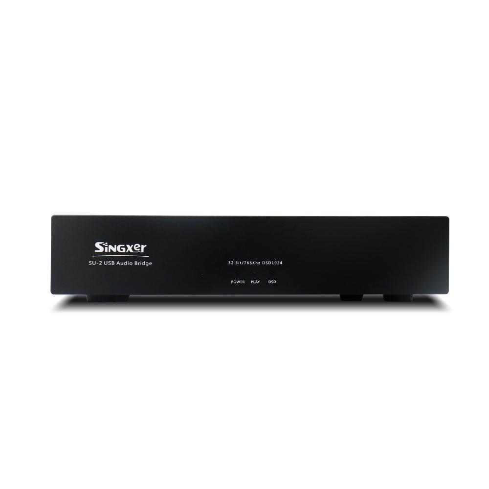
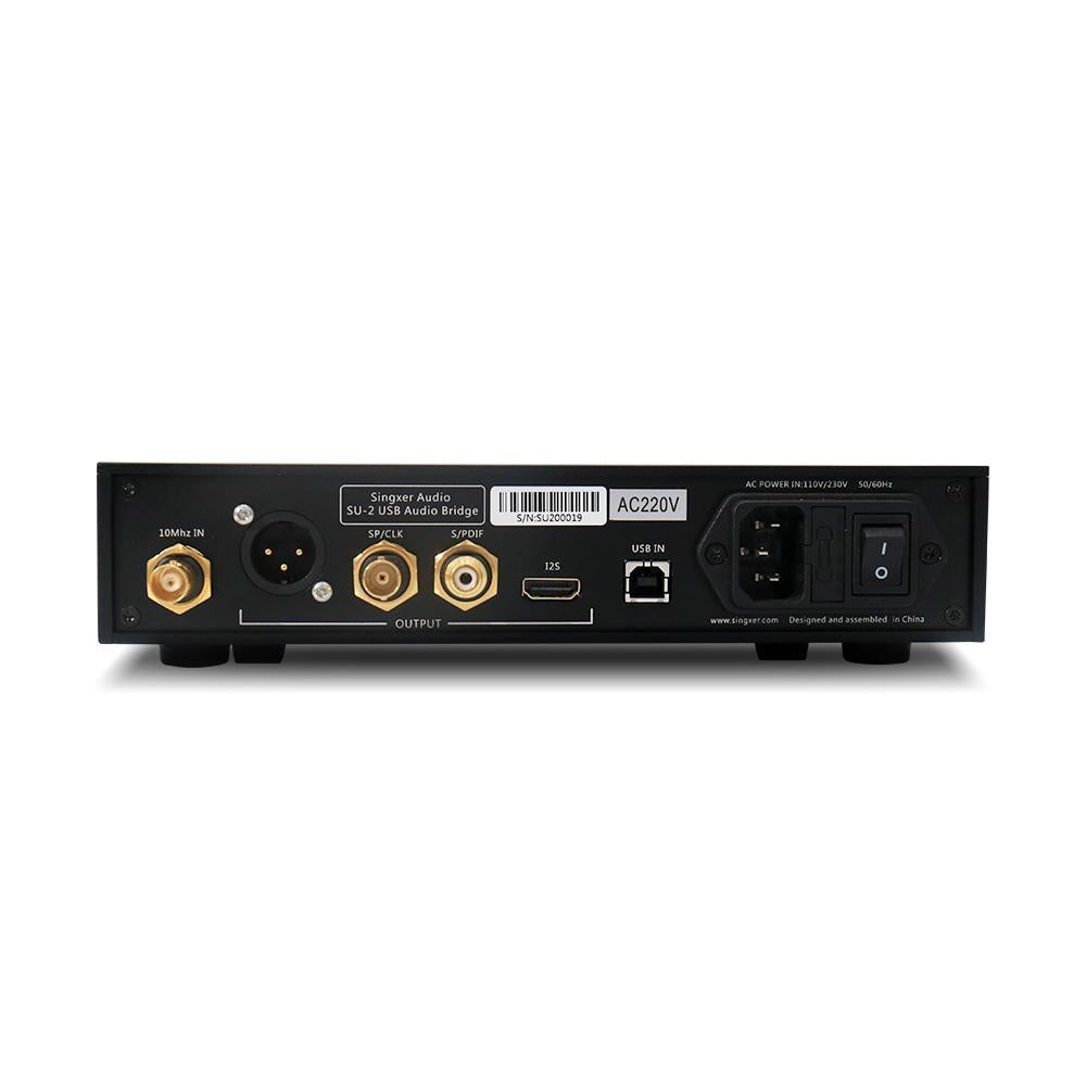
The Singxer SU-2 is a USB digital audio interface that can also be used as an independent master clock. It comes with the latest ARM Cortex-M4 that controls the USB data and also uses a ultra-low jitter clock system. Among the various outputs it has, it includes XLR balanced AES, coaxial RCA/BNC, I2S interface with HDMI socket, and a perfect master clock/word clock output. Apos Audio also found that the SU-2 also supports an external 10 MHz clock input using the common 50 ohm input impedance design.
When the SU-2 is used as an independent master clock, it can output a word clock of 44.1K-384K, or output a master clock of 22.5792 Mhz - 49.152 Mhz. It can be used as a frequency converter when an external 10 Mhz clock input is being used.
Note:This is the 110 V version. Please contact us if you are looking for the 220 V version.
I2S output supports all DSD; S/PDIF, AES/EBU support DSD128 DOP mode
Bit Width
Up to 32 bit over I2S output
Up to 24 bit over S/PDIF
USB input socket is a standard USB-B type socket, USB power supply range 4.5V–5.1V
RCA connector outputs standard S/PDIF signal, electrical level is 550 mV (standard connection load), output impedance of 75 ohms
Power supply input is AC 115V/230V
System Compatibility
Windows XP, Windows 7, Windows 8, Windows 10: 32/64 bit, need installed driver
Native Mac OS 10.6 and later: Use own driver
Native Linux with UAC2 compliant kernel: Use own driver
Android OS 4.2 and above: Need support OTG function
I2S Port Using HDMI Output
Electrical level is 3.3V LVDS differential signal
DSD ON signal, 5V power supply, CPLD has processed the mute signal (no need to process again)
DSD ON signal can be user defined, DSD ON signal can be connected to PIN 13, 14, 15, 16 on the socket
Flexible HDMI-I2S Output Configuration
Switch 1–4 is for PIN13–16 on the HDMI socket
When you turn “ON”, it means that HDMI PIN has DSD_ON function
Switch 5 and 6 are clock output mode
Switch 5 “OFF” is MCLK, “ON” is WCK
Switch 6 configures the frequency of MCLK, which is 22.5792M / 24.576M when "OFF", and 45.1584M / 49.152M when "ON". The configuration of switch 6 is valid for CLK OUT, RJ45-I2S, and HDMI-I2S
Switch 7 can set the left and right channels in DSD mode in I2S signal separately
Switch 8 can set the BCLK line sequence in the I2S signal
When OFF, PIN4 is BCLK + and PIN6 is BCLK -
Switch 9 can set the line sequence of LRCLK in I2S signal
When OFF, PIN7 is LRCLK + and PIN9 is LRCLK -
Switch 10 can set the line sequence of DATA in I2S signal
When OFF, PIN1 is DATA + and PIN3 is DATA -
Singxer SU-2 USB Digital InterfaceSale price$470.00 USD